This project is an efficient digital guitar amplifier that takes a high-impedance analog signal (guitar pickup) and converts it to PCM with an ADC connected to a Zynq FPGA. Audio filtering is done on the FPGA's DSP resources and then converted to a Pulse Density Modulation (PDM) signal that drives a 15W Class-D amplifier. The software interface on the touch screen is running a specialized version of Ubuntu Linux running on the dual-core ARMv7 processor within the Zynq-7010 chip. The software writes parameters (volume and tone control levels) to digital logic through memory-mapped registers. The logic is written in VHDL and the software is written in C.

This project approaches creating an amplifier in a new way. No other guitar amplifier uses an FPGA with embedded Linux, Pulse Density Modulation, or Class-D amplification. Existing digital effects processors and amplifiers are proprietary and cannot be disassembled or modified. This design is modular in both software and hardware. The signal path through is entirely defined by code, so adding new audio effects does not require adding new hardware.
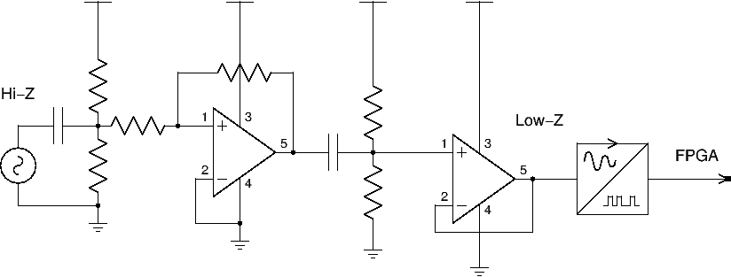
The magnetic pickup coils on an electric guitar are high impedance, and the input to the ADC is low impedance. In particular, the pickup signal must be DC decoupled before being amplified in voltage and current. A series of rail-to-rail operational amplifiers do this.
The Analog to Digital converter chip has a variable input voltage range set by a stable, well-filtered voltage reference. It communicates with the FPGA through an SPI interface written in VHDL.
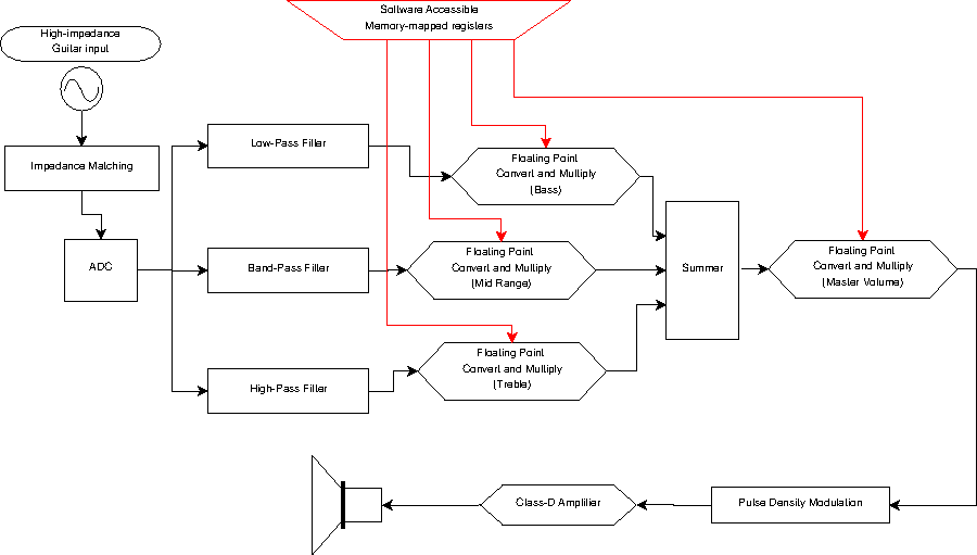
The samples captured by VHDL logic are sent through series and parallel digital filters before they are amplified.
The filters are implemented in hardware by the Xilinx FIR Compiler tool and IP core. This IP core takes a coefficients file produced by the FDA (Filter Design and Analysis) tool in MATLAB.
For this design, the output from each filter needed to be adjustable like the tone controls on an analog amplifier. The output of each filter is converted and fed into a floating point multiplier. The volume multiplier value is supplied from an AXI bus register written to by software running on the embedded CPU.
All three filters are summed together and connected to a Master Volume floating point multiplier. This final output is sent to the Pulse Density Modulation logic that connects to the Class D Amplifier board.
The volume and tone control floating point converters change 16 bit PCM integers into double precision floating point values before multiplying them by values registered from software.
Traditional digital audio output works by setting a PCM value in a Digital-to-Analog Converter, which converts that value into a voltage. That voltage is then amplified by a series of single-ended gain stages before being brought to loudspeaker power by a Class A/B amplifier.
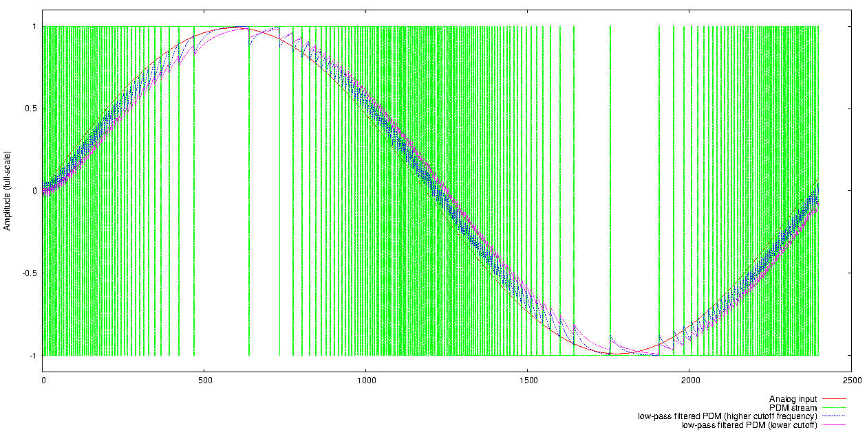
PDM produces a digital pulse train at a frequency many times higher than the sample rate. When this pulse train is sent through a low-pass filter in the audio range (< 20kHz), a smooth audio waveform remains.
PDM illustration: the smooth sine wave (red) is converted to a PDM stream (green). The PDM stream is sent through a digital low pass filter (blue), at a high cutoff frequency, and then the stream is sent through a different low-pass filter with an even lower cutoff (purple).
Class D amplification is closely related to Pulse-Width Modulation and Pulse Density modulation in that it is based on the idea that a pulse train sent through a low pass filter leaves a smooth linear curve. In this project, a PDM signal is sent to the PWM inputs on a Class D amplifier chip.
Class-D amplification is more efficient than traditional amplifiers at the cost of some fidelity.
The Zynq chip is unique in that it has an entire embedded computer system on a chip surrounded by FPGA fabric; its 650 MHz ARM Cortex-A9 processor is complemented with hardware for USB, Ethernet, I2C, and other common buses with open-source linux driver support.
This project was an intense exercise in analog circuit design, digital logic, signal processing, and FPGA development. Though some parts of the project are robust, there are parts that can be improved with more time and planning. Namely, digital filtering and amplifier modeling in hardware are areas where refinement would yield rewards for our understanding and the usefulness of the device. The Zynq FPGA has more hardware resources for signal processing than we are using, meaning we can add more effects with the hardware in this box.
Mentor and Sponsor - Dr. Rich Compeau
Technical Advisement - Dr. Jim Aarestad
Additional Technical Advisement - Eric Hamke, David Modisette, Rick Rothrock, Willard Hemsing